Minty Boost Circuit Diagram
It is a class of what Web here is the final wiring diagram based on wermy's guide for anyone who wants a full picture of what connects to what. Solder it (instructions for version 3.0 kits only!) put it in a case. Web the images below show the assembly of minty boost kit where a jst connector is soldered to the minty boost pcb instead of connecting the battery holder in the kit.
Power Supply Lm2577 5V Boost Circuit Does Not Boost Voltage
The circuit diagram of the boost converter using power mosfet as a switching device is shown in the below figure. As the name suggests, the converter takes an input voltage and boosts it. Web boost converter circuit diagram components required inductor mosfet 1n4007 diode capacitor working of boost converter switching operation what is boost converter?
Installation Diagrams 24 Volt System The Following Schematic.
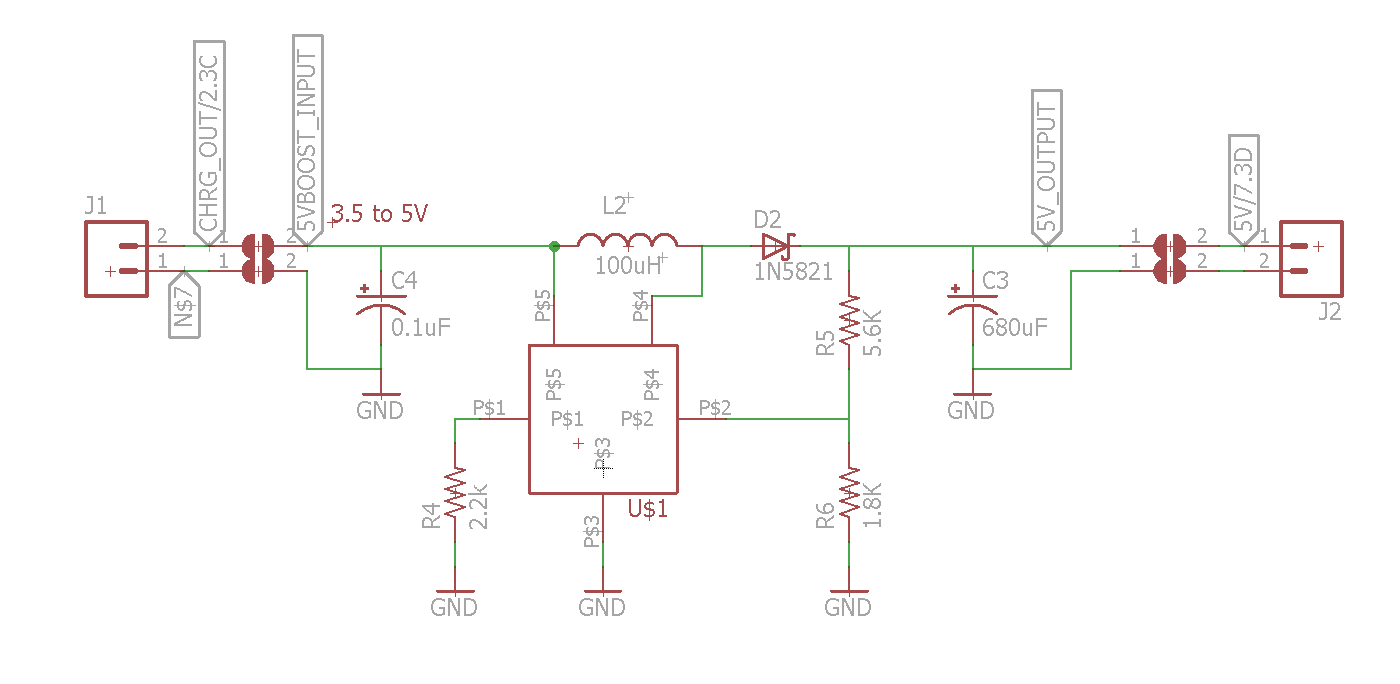
Web the circuit diagram is available here: It's not 100% correct but it's pretty close. The minty boost circuit is allowed to connect to the lithium polymer battery charger circuit.
When Autocomplete Results Are Available Use Up And Down Arrows To Review And Enter To Select.
Web general information about the lithium polymer charging circuit as well as a circuit diagram and data sheet can be found here: The boost regulator produces a higher average output voltage than the dc source input voltage. In this topic, you study the boost regulator circuit diagram, waveforms, modes of operation & theory.
There Were No Data Line Resistors For Pulling Up Or Down But It Worked With Most Things.
Web meta documentation this page details how i went through the process of coming up with the idea, hardware, design, etc. Since this project only took 2 days (on & off) to design/test/release, it's a lot easier to keep track of than something enormous like the x0xb0x. Web boost regulator circuit diagram, waveform, modes of operation & theory.
One Thing To Note Is The Raspberry Pi Actually Sits Above The Controller Pcb, But For Some Reason Fritzing Doesn't Allow Me Order The Components In That Way (If Anyone Knows Why, Please Pm Me!).
Conventionally, red is positive (the nubby side of the aa) and black is negative. Web circuit diagram of boost converter : It consists of an inductor connected in series after which a power mosfet is connected in parallel with the positive and negative terminals.
This Is A Vey Easy Kit To Make, Just Go Through Each Of These Steps To Build The Kit:

dc voltage boost circuit dc current booster circuit Bojler

Mobile Signal Booster using LM386 IC

schematic diagram for booster amplifier

Build a Current Booster Circuit Diagram Electronic Circuit Diagrams
![[résolu] quel programme pour schéma](https://i2.wp.com/midnightengineer.files.wordpress.com/2011/03/minty-boost-schematic.jpg)
[résolu] quel programme pour schéma

I need help with this project circuits
power supply LM2577 5V Boost Circuit does not boost voltage

StompBoXed The Guitar Pedal Builders Repository Keeley Java Boost
